There is scope for cost effective diagnostics, says Pico Technology. When it comes to fault finding electronic units on modern vehicles, a PC, software, and a diagnostic kit can provide the answer.
Over the past two decades, vehicle manufacturers have made huge improvements to the safety, performance, reliability and fuel economy of their vehicles. These improvements, which include higher levels of driver information, are the result of an increased reliance on the use of electronics. However, faultfinding the modern vehicle equipped with an electronic control module or unit (ECM/ECU) can often prove difficult. Franchised garages are either supplied with, or have to buy themselves, high-tech diagnostics equipment so that the auto-technician can ��narrow down�� on what ails the vehicle. For the independent automotive technician, or mobile garage operator, there is a powerful, lower cost alternative available �C the oscilloscope (also referred to as a lab scope).
When Sparks are Flying
The humble scope enables auto-technicians to capture the majority of signals and waveforms found in the modern vehicle �C such as ignition, air-flow, O2, and ABS �C and much can be determined from the captured waveforms as they can represent chapters in a complex automotive, electro-mechanical story.
Figure 1 for example shows a secondary ignition waveform, typical for an engine fitted with electronic ignition, and was captured using a capacitive ignition pickup clamped to a high-tension (HT) lead. The waveform shows the generation of the initial voltage (about 13 kV) required to jump the plug gap (the ��Plug kV��), and the length of time that the current flows across the spark plug gap (the ��Burn Time��). In the trace, it can be seen that the horizontal voltage line (Sparkline) in the centre of the trace is at a fairly constant voltage, about 3 kV, which then drops sharply into the ��Coil Oscillations��.
The trace in figure 1 therefore tells quite a story �C between the Polarity Peak and the end of the Coil Oscillations �C over a period of some 5ms. Had there, for example, been less than four Coil Oscillations it may have indicated that the coil needs replacing.
Bits and PCs
 The automotive test and measurement environment is undoubtedly a harsh one, with an enormous range of voltage and current waveforms to deal with. It is therefore important to have the right adaptors and connectors to hand; otherwise overload and damage can occur. Recording the secondary ignition trace shown in figure 1 for example cannot be done through direct connection. In automotive diagnostics we therefore employ a number of dedicated probes and pickups. Current clamps also play an important role in automotive testing and are ideal for displaying starter current waveforms, charging currents and for performing quick relative compression tests. The automotive test and measurement environment is undoubtedly a harsh one, with an enormous range of voltage and current waveforms to deal with. It is therefore important to have the right adaptors and connectors to hand; otherwise overload and damage can occur. Recording the secondary ignition trace shown in figure 1 for example cannot be done through direct connection. In automotive diagnostics we therefore employ a number of dedicated probes and pickups. Current clamps also play an important role in automotive testing and are ideal for displaying starter current waveforms, charging currents and for performing quick relative compression tests.
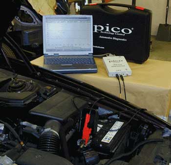
Because numerous cables and adaptors are required, it is often handy to have access to a dedicated (electronics) faultfinding kit. Pico Technology for example bundles all of the necessary fittings and cables required for automotive diagnostics into a dedicated kit. But the star of any automotive diagnostics kit has to be the scope itself. Both waveforms shown in this article were captured using Pico��s ADC-212 analogue to digital converter which, when used with the Automotive software within PicoScope (provided FREE), converts a desktop or laptop computer into an oscilloscope, spectrum analyser and a digital multi meter, all at the same time.
Pico��s kit also includes a 600A current clamp for monitoring charging currents or starter currents for relative compression testing, a 60A current clamp for monitoring injectors, fuel pump currents etc, a 2 pin break out lead to measure voltages and currents from standard automotive plugs i.e. fuel injector or temperature sensor waveforms.
Waveforms Library on the Web

There are many benefits to be gained from employing PCs in automotive diagnostics. Firstly, Windows-based software is intuitive and easy to use. Also, multiple traces can be displayed at the same time �C ideal for comparing captured waveforms against expected results. Figure 2 for example shows waveforms captured from an inductive pickup on a distributor and the output of an O2 sensor (inset top right ). Furthermore, as we collect waveforms from a variety of vehicles and components thereof, it then becomes possible to build up a library: this is exactly what Pico has done. The company has made freely available (on its website) a library of automotive waveforms, including those for starter current, injection units, crank sensors and primary and secondary ignitions.
Organised alphabetically by signal type (ABS, Air Flow, Alternator and so on), the library contains waveforms captured from a wide range of commercial and specialist vehicles. Both 'good' and 'bad' waveforms are present within the library because, often, the absence of a good signal does not necessarily give us enough clues as to why it is absent. The inclusion of 'bad' waveforms, all with notes explaining which components are likely to be at fault, is therefore a major plus.
Useful diagrams and photos are also available to, for example, show where to place current clamps.
At present the library contains more than 130 waveforms, all captured using Pico��s Automotive Diagnostics Package, which costs a fraction of traditional automotive oscilloscopes and engine analysers. Packaged in a tough carrying case the Automotive Diagnostics Package can be kept alongside other tools. Whilst vehicle diagnostics is becoming increasingly complex, due to the number and variety of signals that may need to be checked, the use of PCs and access to automotive waveforms is undoubtedly simplifying the task. And with the price of PCs falling every few months and suitable PC-based scopes priced at a few hundred pounds the cost of powerful diagnostic equipment is well within the reach of even the small garage owner.
�������������� >
|